Marine  Magnet Dispatch Service Centre
  • Drone Fleet Readiness Office
  • Status Updates
  • Marine Corps Integration
  • Submit Comments
  • Download Reports
  • Building Drone Swarms

Top 10 Maintenance "Digital Twin" Monitor Conditions Function as Planning Tool for Operators

1/23/2019

0 Comments


Readiness Initiative that’s being prototyped as we speak is trying to take disparate maintenance efforts – field events, depot events, which make no logical sense right now, all they do is guarantee that the weapons systems are not available to the operating squadrons because this week it’s out for this inspection, they return it to the flight line and the next day it’s out for another inspection or modification.

“So right now Navy is working, prototyping Two logical, consolidated depot events to try and guarantee more aircraft availability on the flight line once it comes out of that depot event. So that’s looking very promising.”

Application prototype officials are still “fine-tuning the details of it,” but said that more workforce labour could be conducted while the planes are at the depot – including inspections and maintenance items that would normally be done by the squadron – to consolidate the required work into as few days as possible

Marines will apply Digital Twin predictive maintenance tool to part of its aging fleet troop carriers equipped with diesel engines, heavy-duty transmissions, and other features with hundreds million hours of metrics on diesel engines alone, and in the world of AI machine learning, the more metrics you have, the more accurate your predictions get.

The goal is to track the performance of each major component in real time — oil pressure, turbocharger speed, battery life, etc. etc. — and predict when it’s likely to fail.

Predictive maintenance has two benefits. First, it lets you replace or repair a part before it breaks on you. Second, it lets you skip a lot of so-called preventive maintenance, when you pull your vehicle into the shop after so many hours of operation because that’s when, on average, such-and-such a component will need an overhaul.

Navy is looking for ways to shorten the repair time for not just ships, but planes and combat vehicles too. The ideal behind having less time in maintenance is that in effect you have a larger Navy because there’s more ships at sea. The whole thing is around speed. How do we get speed?

About one-quarter of the Navy’s surface ships are currently going through extended maintenance periods that last anywhere from six months to a year. During that period, major components, like engines, are overhauled. Even ships that aren’t in this extended period of downtime undergo about three to four weeks of maintenance quarterly while in port.

Getting these ships, planes, and combat vehicles out of overhaul faster frees them up for training and deployments, thus boosting readiness and lethality.

The instability — in terms of the availability of ships and scheduling — is probably one of the more complicated aspects of this. If you could get something that’s smooth, in terms of backlog and schedule for the suppliers and contractors, they’re going to be a lot more productive.

Readiness initiatives remain a focus of aircraft programmes in order to increase mission capable rates and decrease operating cost, and maintenance updates, repair capability standup, and strategy changes need to keep up with readiness challenges.

Almost every piece of new equipment types is network-driven. The complexity of modernised equipment forces maintainers to take an active role in the setup, configuration, operation, and maintenance of this equipment.

We went live with an Mobile App that is expected to save time and stress for aircraft maintainers by enabling direct access to the maintenance database from the flight line at the point of aircraft repair. This eliminates the need to secure tools and go to back to the office and log into a static network to document the maintenance actions performed.

“Maintainers didn’t have a convenient way to input their maintenance actions into the system of record. They have to travel to a desktop computer, go through the sign-in procedure for both the computer and the maintenance data system, then they can enter the data for the maintenance performed on the flightline.”

During user acceptance trials testers estimated the app saved a lot of time per day.

“Live data availability is paramount for field units to take swift maintenance actions and schedule work orders as changes are occurring across the flight line. Additionally, returning time back to maintainers is an added benefit as task documentation is completed throughout the day rather than at the end of shift.”

Because the data entry can occur in real time by using the new app, there is a greater probability of accuracy and less steps involved compared to the current steps of writing notes on a piece of paper and transcribing them into the database later from an office.
 
“If we didn’t get PagerDuty alerts, we wouldn’t have a business.”

“I can now sleep at night knowing the right person will be contacted.”

Coordinate on-call schedules across all your monitoring tools, to empower development teams and reduce chronic alert concern in your life

Some of the challenges overcome with development of the app were overwhelming security documentation requirements and connectivity challenges on the flightline. The team was able to create a secure path to take the modern technology and interface with a legacy database system securely from almost anywhere.

“Over the past couple of years there has been a paradigm shift from desktop computing to mobile. This application provides a friendly and easy-to-use interface that is familiar to an everyday mobile users.

The app performs the same desktop computer actions on a handheld device and typically more efficiently by utilising on-legacy devices.

Maintenance officers will be crucial to transitioning to new equipment and training readiness model by providing the subject matter expertise allowing operators to successfully employ their weapons system. The enlisted maintainer of the future will have to be agile enough to adapt to the potential for rapid changes in capabilities and system implementation.

Maintainers will also be required to be competent in basic readiness update status link implementation as operators. Link/align schedules between the roles of the operators, maintainers and tactical users will continue to be essential for success in all future missions.

Many weapons system products have lifecycles spanning multiple decades e.g., aircraft, ships, power generation equipment with design repositories and digital product lifecycle systems models readable most of the time.

Digital product models can have longer lifespan than information formats, application and computing platforms used to create the model. And info must be writable as well as readable if a digital product model, or its supporting information, needs editing at some point during the product lifecycle.

There’s been a small blitz of media coverage of the contract, but it’s focused on how predictive maintenance can improve efficiency and cut costs, but there are uniquely military benefits.

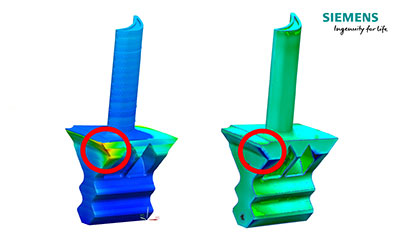
Digital Twins provide a valuable opportunity to simplify and improve things. It is not just a question of gathering more data, but rather of turning that data into useful insights. To take one example, countless sensors installed throughout major weapons systems measure values like pressure, temperature or flow rate. If this information is linked with intelligent tools a detailed picture of the entire fleet and its individual process flows emerges.

The difference between a “Digital Twin” construct platform and a traditional model or simulation is that the “Digital Twin” is responsive—it receives information from sensors on the physical asset and changes as the asset changes to yield a real-time model of the asset and its performance by looking for inconsistencies or non standard patterns and find problems that may not be easily identified through visual inspection or other traditional methods.

Reliability model addresses problems of accurate sensing, parallel actions, action conflicts and efficient distribution of resulting shared state of the simulation. We have implemented the core of concurrent logistics processes including the rollback problem, virtual time local to the agent, load balancing and implementation of interest administration.

Digital Twin simulations have definite applications for designing reliable equipment. For example, based on Digital Twin design status updates, a virtual copy of the product can be "produced."

Maintainability engineers can then enter a virtual design space where maintenance can be "performed" on the product.

Accessibility of components, whether an item fits in an allocated space, and the approximate time required to perform specific maintenance actions all can be evaluated using Digital Twin Simulations.

Virtual copies of support equipment can be evaluated by "performing" maintenance activities with them. Digital Twin Simulation reliability updates could allow technicians to view virtual information panels "superimposed" using augmented reality techniques on the actual equipment.

Virtual Reality can be used to check machine status at a glance, or as a visualisation tool in planning out installations. Perhaps most intriguing of all, VR can be used for remote expert support, giving the engineers at HQ the ability to “see” through the eyes of workers in remote locations.

The advantages of VR have been demonstrated in the context of Maintenance, Repair and Overhaul MRO applications. For example, the ability to enter information via voice input in place of pen-and-paper checklists can streamline inspections and maintenance routines.

Experienced workers equipped with VR devices can narrate routine maintenance and inspection tasks as they perform them, enabling companies to build up libraries of instructional materials over time with relatively little effort.

Eliminating the need to switch back and forth between a task and a checklist for that task could also reduce the risk of error by keeping inspectors and maintenance technicians more focused.

The ability to overlay a worker’s visual field with step-by-step instructions—including animations depicting the proper assembly or disassembly of parts—offers the potential to reduce lead times and error rates in MRO operations.

Remote expert advice is an obvious application for VR in MRO. Field service often requires experts to travel to remote worksites, but the telepresence afforded by VR means a single expert can service multiple sites without ever having to leave the office.

It’s been said that there’s no substitute for a hands-on education, but whoever said that hadn’t see what VR can do. Many of the biggest players in manufacturing have begun to take advantage of what this unique technology can offer.

Simulation for industrial robots is a valuable tool for robotic system integrators and robot programmers, allowing users to design robotic work cells and generate robot programs through offline programming.

However, simulation requires accurate digital models of each piece of tooling and equipment in order to be useful. In most cases, users must export files from legacy tools, then import them into the simulation space. However, as any professional user knows, exporting, importing, and managing different file types and compatibilities can be a headache.

VR plugins are designed to make tasks easier when programming for welding, drilling, machining, setting approach angles, and for importing many parts from legacy systems to simulation more rapidly.

For example, when welding assembly is loaded into the simulation, knowing the exact position of welding joint start and end points can be challenging. Using the plugin, the user selects the surfaces, points and edges surrounding each weld. Next, the assembly automatically appears and the welding program is generated. This generated program can then be edited.

Next, the video illustrates how a common workflow for importing a model into simulation involves saving the part in a different file format before it can be imported. With the plugin, the user can click a button in the toolbar, and the model will automatically load.

In the future, condition-based monitoring will allow agents to identify incidents before they occur. Intelligent forecasting will also ensure that spare parts can be ordered in good time, enabling agents to plan turnarounds, maintenance and repairs more quickly and easily than ever before.

Given the current state of an asset, the Digital Twin model uses predictive learning technology to proactively identify potential asset failures before they occur. Using artificial intelligence with advanced process control, control strategy design and process optimisation, the necessary variations from process and asset design are fed back to the engineering stage of the lifecycle enabling a complete and efficient digital value loop.

At each observation moment to build reliability model, an indicator of the underlying unobservable condition state assessed, and the monitoring information is collected. The observation process is due to a condition monitoring system where the obtained information is not perfect so observation process doesn't directly reveal the exact condition state.

Depot maintenance on aging weapon systems, including Navy and Marine Corps aircraft, becomes less predictable as structural fatigue occurs and parts that were not expected to be replaced begin to wear out.

To match value of indications to the unobservable degradation state, a relationship between them is given by an observation reliability model. Time-dependent proportional condition state is considered to model equipment failure rate. Reliability Model Limitations include the problem of imperfect observations, and the problem of taking into account the condition state history of observations.

Amount of performance fatigue life consumed and the remaining life for each aircraft in the fleet is assessed. One of the greatest benefits of an individual aircraft tracking program is that calculated independently of other aircraft in the fleet. Reliability Models based on individual design characteristics reveals loads monitoring can take place without a prior knowledge of the exact critical location.

Ideally, provided that wide spread in the rate of fatigue usage, sufficient number of primary load carrying structures are routinely monitored, stresses at all critical locations hours on many aircraft. The fatigue accumulation rate is the individual aircraft fatigue damage values

Critical transfer function relating the monitored load are calculated using the standard location stresses. So change in the critical location an be accommodated through the design of transfer function to the new critical location. Some of the benefits gained from the individual aircraft tracking program include:

1. Modeling of operations to stabilise the rate of fatigue life consumption,; life of an aircraft structure, knowledge of the actual load experienced by that structure is essential.

2. Drawing reliability comparison between design and usage spectra for each aircraft; with estimation of the fatigue life or damage status of major components on each aircraft based on loads monitoring in the primary structure of that aircraft and related to fatigue test results

3. Planning of maintenance action according to rate of fatigue damage accumulation for aircraft fleet reliability estimates, modification of operations to stabilise the rate of fatigue life consumption, life of an aircraft structure, knowledge of the actual load experienced by that structure is essential.

4. Building an operational load reliability model in conjunction with flight trials for application to a fatigue test and, where a safe-life may be stipulated, some aircraft are retired at a different number of flight hours due to their to compare with early fatigue test metrics

5. Identifying the variability in response between aircraft calculated rate of fatigue damage accumulation being higher or lower than the reliability target rate because of operating fleet under the same flight conditions through assessment of mission severity, with prime factors driving individual aircraft tracking are the unique combination point-in-the-sky affects

6. Gaining better understanding of the loading scenario experienced by different aircraft in the fleet and the availability of a good on-board reliability monitoring in conjunction with flight trials metrics

7. Observing difficulties introduced by assumption that, if the fleet average load factor exceeding curves matched that and structural redundancy at vertical tails of the design spectrum, the aircraft could be: operated until the design life, but operators of modern aircraft is likely to have a different systems

8. Designing future aircraft to be smart buyers in the acquisition of new aircraft for the same role; and usage spectrum to the design spectrum. The root bending moment of the component is the primary factor to assess.

9. Defining flight trials metrics parameters to be measured on new aircraft or new monitor and fleet-wide average load systems for the same aircraft to allow the more accurate calculation of critical components reliability

10. Seeking to maintain fleet structural integrity based on its reliability and identify operational overloads making individual aircraft tracking programme necessary. Test life extension must be substantiated by further fatigue tests to determine the next critical location and required repairs


0 Comments

Top 10 Sustainment Strategies Tools Guide Support Plan Implement Activities Over Service Life

1/23/2019

0 Comments

 
Navy/Marines faced with decision to accept less reliable and maintainable aircraft than originally planned. Among other outcomes, this could result in higher maintenance costs and lower aircraft availability than anticipated which also could pose readiness challenges in the future.

A key to making it all work is having the budget to pay for the maintenance work. If it takes less time to go through maintenance, it costs less. If it costs less, there’s more ships available and the shipyard can put more ships through there, everyone is a winner.


At a high-level sustainment strategies are aimed at integrating requirements, product support elements, funding, and risk management to provide oversight of the aircraft.

For example, these sustainment strategies can be documented in a life-cycle sustainment plan, postproduction support plan, or an in-service support plan, among other types of documented strategies.

Additionally, program officials stated aircraft sustainment strategies are an important management tool for the sustainment of the aircraft by documenting requirements that are known by all stakeholders, including good practices identified in sustaining each aircraft.


In Live-fire excercises we’ve noticed partners tend to under invest in simulation training for expeditionary logistics/ sustainment. That creates a whole mess of problems. What we don’t want is for major weapons systems to “turn into a paperweight down the road, and the only way that we can fix that is by making sure we’re having good, candid conversations about Sustainment Simulations up front.”

Must push services to focus on upkeep of existing goods, rather than chasing the shiny object,” The fact that equipment deployment comes with a long tail of sustainment and logistics training is a point Pentagon officials need to make use when discussing deployment of weapons systems.

Our office now has a system in place where “we can see the kind of sustainment we’re providing to every partner we can see the sustainment profile of each system which is going to allow us to then have the dialogue to show them ‘this is what you look like, this is what you bought into, this is the performance level, or this is where you need to contribute more to planning of sustainment phases of expeditionary exercises.

Part of that pitch involves arguing that sustainment logistics isn’t just about maintaining what you have, but opening up future opportunities. We have emphasised increasing capability for existing systems. The argument is such that as those capabilities come online, the better maintained your equipment is, the better chance you have to load new technologies onto older platforms.

Due to funding shortfalls, the services have reduced contract support levels, intermediate level repairs, and ability to provide after-hours support in specific areas. Although extensive efforts have been expended to limit adverse impact to weapons systems undergoing maintenance, fiscal realities have forced us into these actions.

Specifically, we are forced to stop engineering support to include tank and void inspections, infrared surveys, underway vibration analysis and availability work certifications.

Reduction in parts procurement means a stop to all major diesel work, torpedo tube repairs and refurbishment, air compressor overhauls, communication receiver and transmitter repairs, and repairs to electronic warfare and anti-ship missile decoy systems.

Maintenance optimisation models maximise balance between cost/benefit of maintenance. For given system with failure rate profiles of its components and the available maintenance resources, maintenance optimisation model provides the answer to questions like:

“What is the optimal number of maintenance tasks required on this piece of equipment for a given time horizon?”

“When is the appropriate time to execute maintenance action?”

In more complex cases, optimisation model also includes decisions about the spare parts policy for components and estimating number of maintenance crews required in given shift.

Capacity for applications described in this report currently consider only subset of missions and focuses on equipment-specific planning factors.

Future work will expand application to include other missions and will include additions or process advance of existing features—for example, the addition of a consistency test for relative task importance selection.

The first challenge is how to deal with common tasks when considering multiple missions. It may be the case that a single command centre is all that is required to accommodate multiple missions, but the equipment needed to support each mission may differ in some way. In other words, although the task is “common,” there may be unique, mission-specific requirements for accomplishing it.

Second challenge concerns sequencing tasks and assigning relative importance at the task level versus the mission level. A typical example might be transport of equipment to new staging area. If mission A is designated more important than mission B, does that mean that all tasks associated with mission A have absolute priority? If not, how do we provide the user with the ability to designate exceptions at the task level?

Types of vehicles, equipment and weapon systems found in motor pools today cannot be maintained properly without the authorised tools.

Commanders, unit maintenance & supervisors must ensure that all sets, kits, outfits and special tools are being used and maintained properly; properly accounted for; and promptly replaced when unserviceable or lost.

Unit mechanics cannot be expected to properly troubleshoot, remove, or replace components unless the right tool is readily available and serviceable as called for in the equipment task order.

Maintenance supervisors must screen equipment 24/7 level parts manuals to obtain markings for special tools. They must also ensure hand receipts are prepared to maintain accountability for these tools.

Sustainment cost estimates are derived by integrating technical assessment and schedule risk impacts on resources and providing programme life-cycle cost excursions from near-term budget execution impacts and external budget changes and constraints.

Additionally, team attention to risk factors is most effective if it is fully integrated with the programme systems engineering and programme administration processes—as a driver and a dependency on those processes for root cause and consequence control.

One benefit of strategic sourcing is shifting the focus from looking only at the purchase price to understanding the total cost of owning or consuming a product or service. For significant spend areas, new procurement teams must abandon outmoded practice of receiving multiple bids and selecting a supplier simply on price.

Instead, they consider many other factors that affect the total cost of ownership since acquisition costs do not even account for at third of the total cost for most products and services. The balance of the total comprises operating, training, maintenance, quality, and transportation costs as well as the cost to salvage product value later on.

Identifying the total cost of ownership requires looking at the entire process of procuring and consuming the product or service, something that can only happen with cooperation and input from both the buyer and the seller. DoD must not stop there, must also ask suppliers and internal stakeholders the following important question: "How can we work together to reduce the total cost of ownership?"

Establishing a "total cost of ownership" mindset is a goal that DoD supply line teams must embrace and perpetuate throughout the entire enterprise. But it is not always easy to convince leadership to truly prioritise value over price.


Many sustainment challenges have lead to less than desirable outcomes for F-35 warfighter readiness. For example, many F-35 aircraft were unable to fly because of parts shortages. DoD capabilities to repair F-35 parts at military depots were years behind schedule, which resulted in average part repair times that are twice that of the program objectives

Simulation provides for production/maintenance re-planning once the cooperation is settled, with agents informing each other about every relevant change. If the initiator requires a change of product support contract conditions, it informs the subcontractor about its requirements and subcontractor tries to meet the new specification.

If the subcontractor can finish its sub-task sooner or later then agreed, it immediately informs the task originator. When one of agents goes off-line, the connection is delayed and during a next successful connection all accumulated changes are exchanged.

Any partner as well as some kind of independent product support organisation can run agent feedback to monitor and evaluate any cooperation, like asking for communication logs, which can or may not be provided. Available product support metrics can be used for evaluation, measurement and future optimisation of cooperation.

The heart of our product support administrative actions is set of planning resource agents using manufacturing case-specific approaches.


DoD has procured weapon systems in the past without regard for the resources required to support and maintain the system. As the services procured weapons, they tended to focus on performance parameters such as the ability of a fighter aircraft to execute sharp turns or the ability of a weapon to fire long distances.

But weapon systems with top notch performance profiles are of little use to the combatant commanders if those weapon systems are not available for use when the commander needs them, or the services cannot afford to support them once fielded.


Once the system is fielded, actual performance tracking enables corrective actions and adjustments to the product support package as required to achieve Warfighter requirements and to control O&S costs. This is accomplished by continually comparing performance against requirements, defined as thresholds; and expectations, defined as objectives.

Actual equipment and product support performance metrics are used, improving product support strategies to meet field use requirements. This includes updating the assessments to examine actual versus predicted cost and performance, supply chain processes based on actual values to help balance logistics support through a thorough review of readiness degraders, maintenance info, maintenance capability, and product support process implementation.

For example, reliability metrics captured through the maintenance process can be compared, using reliability modeling, to specified system reliability. Those components that are critical reliability drivers can then be submitted for review to determine the most cost-effective risk mitigation strategies.


Must focus on optimising maintenance workload tracking across the enterprise and at Sustainment Centre level across all complexes by serving as a single entry point to outside customers with capability to identify workload capabilities and shortfalls across the enterprise and use this information to pursue new/repatriated workload.

An improved, single-interface solution will serve to share backshop and local manufacturing workload solutions among the complexes, reduce costs, accelerate feedback loops, and develop greater local manufacturing agility
.
Must have a robust and agile single-interface solution that provides optimum visibility and improvement opportunities for the Maintenance Repair/Overhaul enterprise based on capabilities and capacities utilising the guidance reflected in the Technology Repair Centre construct.

Logistics Complexes operate with some different business processes creating conditions where complex cannot provide standardised guidance. Does not have optimum visibility of capability, capacity, or cost across enterprise.

There are many programmes, processes and offices working multiple issues related to capacity, manpower workload and so on, but no aggregated metrics to allow assessments at the complex level. Assessments are performed in a variety of efforts throughout the enterprise but they do not use the same methodology.

Even if complex had good metrics on capability and capacity, the lack of common equipment and tools makes temporary shifts to balance back shop and local manufacturing workload very difficult.


Well-designed enterprise-level Strategic Sustainment Frameworks are required to provide an overall site picture of current and future workload in areas such as backlog of workloads, surplus capacity, manpower requirements by skills, facilities capabilities, machine capabilities and space requirements.

Complex is at risk of discarding essential equipment and skill sets without Strategic Sustainment Teams in place to review in-house repair shop capabilities and verify interdependent capabilities are retained before restructures or consolidations. There is no enterprise level strategy in place to review any potential short or long-term workload reassignments.


DoD has limited visibility into the support that the contractor will provide along with the actual costs for which the services are responsible, until after the contract is signed. These transparency concerns are complicated by the fact that the services are paying into shared pools for F-35 sustainment, and the costs they are being charged for some requirements—such as for spare parts—cannot be directly tracked to an item that the services own or support that is specifically provided to an individual service.

Many parts on some aircraft that need to be repaired and replaced that were not accounted for during initial sustainment analysis. To mitigate some challenges associated with the age of the fixed-wing aircraft, Navy program officials have decided to extend the service life of some aircraft by repairing and overhauling airframes and components, as well as developing the engineering specifications for parts that were never planned to be repaired or replaced
 
1. Shortages of spare parts partially result of delays in the establishment of depot repair capabilities

2. Incomplete plans and funding did not account for the long lead time for parts

3. Insufficient amounts of service funding, and poor reliability of certain parts

4. Challenge related to poor reliability of certain parts to include parts that are breaking more often than expected

5. Large number of parts being sent to the depots for repair that do not actually need to be repaired

6. Challenges with squadron-level maintenance troubleshooting.

7. Difficult to improve production and repair capacity of suppliers

8. Timing of the military services’ funding authorisations not aligned with required lead time for parts status updates

9. Planned funding and contract awards still forecasted to be later than needed to meet demand for new parts

10. Parts shortages are expected to continue and may worsen if DoD and contractors cannot implement corrective actions
0 Comments

Top 10 Product, Production and Performance "Digital Twin" Sets Consist of Multiple Virtual Models

1/13/2019

0 Comments

 
The concept of “Digital Twins” is beginning to expand beyond just the notion of a virtual product. The idea of the digital twin is that all of product data is contained together, from initial design files through simulation and materials data. Finally, data about the product’s performance in the field will also be added. Lately, the term is also including the product’s manufacturing data.

The twist that makes the Digital Twin concept important is that computers have greater predictive skills that humans working with physical prototypes. “The digital twin a good definition of what we do. It’s a virtual representative of a physical product or operation.

The point is the precision we can reach. A lot of our technology acquisitions have been in simulation, test, and electronics. If we can improve the precision of the models we’re creating, we can predict performance.”

Prediction is the key to the Digital Twin. If a computer can calculate and predict how materials perform, that computer can create the optimum configuration for the product. System level simulation is predicting how we expect that system to perform. Design requirements can be improved and move into the design phase with a higher set of requirements.”

As the data is moved through design and into test, the original design files remain attached as part of the Digital Twins data. “The Digital Twin comes with CAD and tool development. That gives a lot of information to the downstream processes.. If we understand the language of the product from its inception, we can see if it is meeting the desired threshold and how it will perform in the future.”

The goal is to create a model of the product that not just downplays the need for a physical prototype but actually surpasses what a prototype can provides. We can see the Digital Twin as many twins – the 3D simulation through the product in the field. All of that feeds back into the Digital Twin model. “If you look at the physical design, it’s generative design. Let the computer look at weight or aerodynamics. The physical analysis, the tech systems create the shape based on the constraints.”

The Digital Twin in the manufacturing process brings together two virtual worlds, the digitised product and the digitised shop floor processes. Beyond that, data relating to the supply chain is also part of the mix. “Using the Digital Twin of the factory, we can see how the factory is performing by looking through all of the data. We can look at future orders and create a model of how the factory would need to perform to meet the projections and thus predict the future.”

Take aerospace as an example of how a Digital Twin can assist with the performance and maintenance of a product. One application is to create a Digital Twin of every plane the comes down the line. We can understand the precise configuration that operates at any given time and create a Digital Twin to support the maintenance of each plane.”

The Digital Twin technology can benefit a wide range of industries, but it is particularly well suited to high volume, high mix products. “All of the discrete industries are benefiting from Digital Twin technology now. The industries benefiting the most are those ones what put a large emphasis on physical design like aerospace, To create a high-volume production run, you have to have high reliability in the model. Precision level is your confidence level. The Digital Twin has to be accurate.

A virtual reality function in the Digital Twin package may help in replacing the physical prototype, since it will give users a powerful sense of the product. “We use augmented and virtual reality to impact the feel of the aircraft. In the near future, there will be more confidence in viewing a product in virtual reality. They’re doing that in the test phase. In aerospace, physical prototypes were the name of the game, but we were going to get more accustomed with looking at the product in the digital world rather than as a prototype.”
 
Others define a Digital Twin as digital replicas of different assets, processes and systems in your business which can be used a number of ways. This generic definition is basically correct. However, a Digital Twin is more accurately described as an integrated set of digital replicas or models driven by a rich information model called a digital thread.

A true Digital Twin is not a single model of the asset, even though it’s referred to as a singular “Twin.” It consists of many mathematical models and virtual representations that comprehend the asset’s entire lifecycle – all the way from ideation, through realisation and utilisation – and all its constituent technologies, including electronics, mechanical, manufacturing and in-service performance.

We refer to a set of Digital Twins: Product, Production and Performance. Each of these Digital Twins consists of multiple virtual models appropriate for the given product and production system.

Accurate Digital Twins comprehend the interactions between all aspects of the product and production system. Digital Enterprise Tool was built on our Innovation platform, enables the creation of the most accurate, comprehensive Digital Twins possible.

Product Digital Twin. A Digital Twin for products is typically created using our Systems Driven Product Development 
tech, which drives the creation of intelligent 3D models. Technologies like Convergent Modeling, Generative Design  and Predictive Analytics are the basis for these intelligent models.

Key enablers for System Product develop tech include our comprehensive, semantic digital thread data model, as well as a complete set of integrated tools to help you create model-based system representations and accurate Digital Twins of the product, and these Digital Twins are able to comprehend the impact of design changes on the production system.

A product Digital Twin will typically include electronics and simulations applications, finite element structural, flow and heat transfer models and motion simulations.

Product Digital Twins also rely on predictive engineering analytics, which applies multidisciplinary engineering simulation and tests with intelligent reporting and data analytics. These capabilities lead to digital twins that can predict the product’s real-world behaviour throughout its lifecycle.

Predictive engineering analytics includes tools manufacturers leverage to expand traditional design verification and validation into a predictive role that supports system product development. The ultimate goal of implementing a predictive engineering analytics strategy is delivering innovation for complex products faster and with greater confidence.

Production Digital Twin. The Digital Twin for production uses many of the same tools and techniques to create a twin of the production system. Production Digital Twins, like product Digital Twins, can include 3D models and predictive analytical models as well as production engineering specific models that use tools for conceptual design and virtual commissioning of smaller Production Systems and Machine Tools
used to engineer and virtually commission large production lines.

Performance Digital Twin. The Digital Twin for performance is based on tools enable insight discovery, analysis and monitoring from in-service products and production systems. Performance Analytics quickly identifies product issues disrupting the supply chain, manufacturing process or customer experience.

The performance Digital Twin may also include data analysis to discover hidden product issues before they occur; graphical displays to clearly identify potentially problematic configurations; and automated data monitoring to fine-tune operations and provide insight for improving your products.

Virtual Product Development is used to develop a product heavily – but not exclusively - relying on digital representations throughout the whole or a part of the project’s life cycle. The term “virtual” expresses that it does not yet exist as real hardware, that in fact it is not touchable.

Virtual development makes use of many tools for layout, geometry generation, calculation and analysis, test and evaluation including the management of digital data.

This suite enables to concurrently anticipate a lot more considerations sooner for product and process design than in earlier days. Although mostly relying on and working with approximated data, calculations and simulations today come close to verification and qualification test results.

The Digital Mockup is a core element in Virtual Development, as it is the culmination of the design intent that gives the product an “early face”. If Virtual Product Development is the unifying concept and approach, Virtual Prototyping actually is the process of digitally testing and evaluating the virtual representations of the product in all aspects of developmental and operational life. So the Digital Mockup is embedded in a spectrum of prototyping activities, which aim to mature the product as fast, as less costly and as reliably as possible

Construction of Hardware Mock-ups has been an integral part of any complex product development. A Mock-up is traditionally a hardware or physical model of a component, an assembly or an entire product. It can be full-size or a scaled model of metal or actual production hardware. All military airframe integrators use Hardware Mock-ups to evaluate and verify the design, train personnel or present them to customers.

Major Hardware Mock-ups activities involve the assessment of space allocations, detailed part fitting checks, interference and clearance studies, part installation and removal and assembly verification. A Hardware Mock-up as primary tool for determining lengths of electrical harnesses and for fitting tubes, hoses and other routings into a densely packed structural space. Maintenance checks could also be run with them. Mock-ups for marketing purposes still represent an important means in the commercial business and are likely to do so for quite some time.

Hardware Mock-ups, though having been standard and successful industry practice for a long time have a number of shortfalls that are better addressed with their digital substitutes. In fact, they are only an assurance that everything will fit together, in former times based on drawings.

No “pre-mock-up” investigations can be run. Update with modifications or duplications are expensive, as always a physical component has to be produced. The response to changes is relatively low except for minor ones like drilling holes and there is an inability to reflect real-time configurations.

So the mock-up is usually representative only for one aircraft, and is of very little use afterwards e.g. after certification. Last but not least, maybe the major issue, it is quite costly. There are design, labour and maintenance hours to be paid for, not to forget tools and all the materials. In addition, it consumes precious factory floor space.

The majority of Digital Mock-up applications, as the classical substitute of Hardware Mockups, cover the geometrical and functional areas. The closer one tries to assess the behaviour and interactions of the product in its environment the more will efforts shift to the right end of the spectrum.

Commercially available Digital Mock-up, Digital Simulation tools and Virtual Manufacturing/Digital Factory tools have matured as they cover most requirements for geometrical and functional assessment, and, to a lesser extent, operational constraints.

Shortfalls have to be compensated either with specific tools e.g. for tolerancing, tool developments or with physical specimen. To fully cover the whole spectrum requires all design tools to efficiently communicate with each other so that results obtained individually can be compressed to an overall view of the Virtual Prototype.

The majority of Digital Mock-up applications, as the classical substitute of Hardware Mockups, cover the geometrical and functional areas. The closer one tries to assess the behaviour and interactions of the product in its environment the more will efforts shift to the right end of the spectrum.
 
1. Baseline

A baseline is an agreed set of 3D and non-3D data at a certain time during development that is used as the reference for all design activities. It represents a preliminary status and is the starting point for the next iterations. It is a configuration of a product or status of product data, formally established at a specific point in time, which serves as a reference for further activities.

2. Change

Term used to identify a definition progress over time with reference to a basic or technical definition of a product managed by means of a modification system.

3. Dual-use

These are technologies, manufacturing facilities and products that have military and commercial applications. Commercially produced items, hardware or software, that can therefore be used, with or without adaptations, for military equipment.

4. Effectiveness

The effectiveness of a system is a quantitative measure of the degree to which the system’s purpose is achieved. Effectiveness measures are usually very dependent upon system performance.

5. Iteration

A repetition and rework activity that encompasses multiple passes for the design to converge to suit an array of sometimes conflicting specifications.

6. 3D Master Model

A Master Model is a set of digital 3D data-- surface or volume used as the basic reference for design and/or manufacturing. It progresses during development and when fully detailed it becomes the input for production, documentation and verification activities.

7. Modification

Any controlled change by the Modification system to the definition of the aircraft or equipment whose introduction affects airworthiness/certification, operational serviceability, customer or own company contractual/financial considerations.

8. Pilot

A pilot is a near term demonstration project. It can be a proof-of-concept and a preoperational assessment. Done in laboratories or usually in small-scale business units it serves to find out flaws in the behaviour of the system under operational or near operational conditions.

9. Prototype

A prototype is the first or original example of something that has been or will be copied or developed. It is a model or preliminary version.

10. Version

A specified customised definition of an allocated aircraft within a given production standard/model.

0 Comments

Top 10 Stages in Internal Design Team Build of Sketch Models/Prototypes Create Run Samples

1/13/2019

0 Comments

 
When utilising Design Tools, one of the common requests is why can’t it be more automatic. There are many people that would like to simply load a model, and have the tool determine the best way to mill it, then automatically program it.

While this “Fantasy World “ of design programming may not exist for all types of parts, that precisely is one of the goals of Automatic Feature Recognition. To sort out common elements of the 3D model and using rules and templates, create the code on the part.

Solid models have all the necessary information to describe a parts shape. Users should not need to waste time re-creating part data just for the CAM system. Most prismatic parts are comprised of standard features such as holes, pockets and bosses. Where other CAM systems may require users to define geometry, create boundaries, and then specify cutting operations, automatic feature recognition eliminates that. Typical 2D parts can often be programmed in just a few minutes, versus an hour or more.

Users can typically run a wizard to automatically find and sort the different features within their part. Typically input the stock material size, give it an initial tool orientation and then the tool analyzes the solid model and creates machinable features for machining.

These features will then be listed and automatically sorted for logical machining operations. Alternatively, users that wish for fine control may select the features themselves interactively, and sort them manually. Usually the best approach is a combined approach of utilising automatic feature recognition with some interactive selection or sorting of features for their specific preferences.

Once features are defined, they are sorted for machining efficiency and then they can be machined with strategies ideal to the properties of the individual feature. For example, an open pocket may be machined with a different strategy than a closed pocket. Or shallow bosses will be milled differently than tall ones.

the features are found or selected a three-step process or wizard can be used to program parts utilising the features. Users first select from a list of features so you can input information on shapes and sizes. Next users select a preferred machining strategy based on the information provided, or go with the recommended strategy. The programmer can accept the strategies suggested based on the type of features for rough, semi-finish, and finish passes, or make changes to fit the machining needs for that particular part.

The combination of feature dimensions, stock material, and cutting strategies are analyzed allowing the tool to recommend the most efficient cutting tools, toolpaths and feeds and speeds for each cutting operation. The programmer can choose the recommended tool or search for another tool in the library. Users can accept or change the recommended feeds and speeds.

Although automatic programming provides a good starting point, users should still retain control over how the tool generates its CNC code. Users can set machining preferences ahead of time for the CAM software to apply to future jobs. Although it recommends tools, feeds, speeds, etc, the users can override it with their own preferences at any time.

Automatic feature recognition can extend beyond using just the tool axis. Utilise multiple setup orientations to find all features on the part, regardless of the orientation. These will then be sorted by workplane, and feature type.

Users can then decide the order of various orientations they prefer to use, and program the features accordingly.

Based on your manufacturing knowledge, automatic feature recognition intelligently makes decisions for you. It automatically selects your tools, stepover, stepdown, and more, providing programming consistency, utilising parameters out of the box, or those that you customise for your own operations. These parameters, among others, form part of your operation.

As you create multiple features, the tool dynamically updates your process planning. Providing an optimal machining order, based on what you want to achieve.

Part changes are an inevitable fact of working in a job shop. If a part has already been analyzed and programmed, than the part geometry changes, one can simply compare the updated part to the original. Feature list will automatically update for the changes, and the generated code will update.

This strategy is not only useful on part changes, but when milling similar parts, or a family of similar parts. Simply utilise automatic feature recognition to sort and program one part, tweaking with your personal preferences, then apply all of those same strategies to a similar part, automatically.

Automatic feature recognition allows for standardisation of the entire machining process. The best expert machinists could set up the machining templates; and all programmers, regardless of experience, would be able to utilise their knowledge and experience. This allows for consistency in your finish, tool life and overall quality of parts produced.

Automatic feature recognition and feature based machining can simplify the machining processes of certain parts typical to the job shop, allowing for programming to be completed in minutes instead of hours. Knowledge gained during the process can be retained for future jobs, for your individual preferences

Previous workflows required engineers to create multiple sketches linked together to form a part that was organic in nature. Direct modeling allows engineers to simply push, pull, twist, etc. to manipulate a part. It meets the needs of the fast-paced design industry and allows engineers to create without the traditional boundaries of parametric modeling.

Many engineers in modern design operate mainly in the direct modeling that is not just about creating cool designs, it also is about having the power to edit your parts without neglecting physical characteristics of the design.

Direct modeling allows you to adjust a design organically without worrying about voiding certain necessary parameters set earlier in the design. This ultimately means that when a designer needs to alter a product per the client’s request – or any reason – it becomes an easy process.

Pretty much all of the modern design programs have direct modeling integrated into them. It’s a workflow that is just too essential to the modern engineer. You can use direct modeling techniques to move, rotate, resize, or scale features from imported geometries. The easy push/pull controls allow designs to be modified for quote. All of this functionality ultimately leads to faster iterations between simulations and directly editing the geometry.

The aerospace industry has always been on the forefront of technological developments and tends to be an early adopter of new technology. Even if these new technologies are only used initially on their concept vehicles or in high-performance racing vehicles. The massive manufacturing advances being made across the board point to a future of energy and cost efficiency, and generative design has placed itself firmly in the middle of this revolution.

Generative design is machine-learning-assisted design and is used to optimise a given design based on a set of user-specified parameter and iterative design solution based on external factors. It must not be confused with topology optimisation which is focused on improving an existing design.

Generative Design takes manufacturability into account when creating all the different configurations so you don’t end up with a good-looking design that would be completely impractical to manufacture. Another advantage is that homogenous parts can be created that replace sub-assemblies of multiple different components.

Multiple configurations are presented to the designer and each of these configurations meet all the criteria in different ratios. The designer can then choose the best configuration. However, if additive manufacturing techniques are being used then it is not necessary to do any modifications on the part as it can be directly printed.

Generative design has massive potential since there are thousands of components that make up a vehicle, and many of these can be revised using this system. There are many benefits of using generative design for vehicle engineering, such as cost efficiency since components use less materials, less energy and less time.

Usually components are designed and put through extensive simulations to verify the design, thereafter the part is tweaked and simulations are run again. With generative design, the simulations are run during the design phase and each of the thousands of iterations created have already passed a strength test.

Design Modeling tools have advantage of reducing time spent on the development of conceptual designs since 3D model is generated as part of the process, freeing up the designer to focus on more top-level design concerns. Once the designer decides on the final configuration, it can be slightly modified to meet designer preference.

As a designer, you need to look at what the factory does with the CAD and the interactions between the design team and factory, along with the creation of the instruction manual and sales & marketing material.

The differentiation between designer and CAD modeler varies depending on the size of the organisation or studio undertaking the design in question. In some cases a designer may take their designs to the CAD stage by themselves.

In other cases a specific CAD modeler may be employed to take on this part of the process. This can vary depending on work load, skill set or even the specifics of an individual design. In any case, the designer will remain plugged into any decisions and deliberations.

Maintaining design integrity is often the most important skill required. A CAD modeler is often asked to demonstrate some 2D concept capability, in addition to their core skills, before they're employed to make sure they're capable of following the design language into 3D.

There are many stages for a design to go through before it ends up in the hands of end-users. After a two-dimensional idea has been explored and resolved, the next fundamental stage in the process is the use of CAD. 
You will learn the differing uses of 3D in the design process, and look at how the role of the designer and CAD modeler comes into play as they work through the stages of getting a sketch into a form that can be used to generate a finished product.

Turning a sketch into 3D is a fairly simple process; all you have to do is add the third dimension. Doing it really well and maintaining the designer’s intent, however, is an entirely different proposition.

At this point in the process, you now have a solid design foundation to base all CAD upon modeling. 
You have detailed drawings and illustrations that depict several angles of the chosen design, along with specific details and technical features being noted and explored by the design team.

The factory will take over the CAD and truly engineer the design for most of the above points. The factory will also identify areas to strengthen in order to avoid failure during use and drop testing, consider production issues, such as the number of parts, and assess the production technique in order to minimize costs.

often have a habit of taking the most direct route to a 3D solution, which tends to be a straight line. Straight lines rarely exist in good design. So before the designs are handed off to the factory, the CAD modeler and the designer work in tandem to get as close in 3D to the original 2D design as possible.

1. Keeping the Curves

This stage is set of curves moved into the correct three-dimensional positions, known as a wireframe with no surfaces being built. This is a ‘quick and dirty’ process, much like a first rough pencil sketch, which can feed back into more illustrations from the designer if they’re not happy with certain aspects of the form.

2. Fluid and Flowing

Many tools give you the ability to create fluid nonlinear geometry. They're generally the tools of choice for most studios, as they allow designers to stay true to their sketches before applying engineering constraints. Model sets will often need rebuilding by an engineer or factory team to get to a ‘toolable’ state. Of course, the more experienced the modeler or designer, the less change required.

3. Tight and Constrained

Some tools allow for a high level of engineering from the very first stages of modeling and is often used by factories to create final CAD for tools. To this end, the more technical studios prefer their designers to work within these design spaces to reduce lead time to production. This can, however, result in some loss of some desirable properties since constraints within the tools make it more difficult to create flowing geometry.

4. Organic

Some modeling options are applicable to designs that are of a far more organic nature. Organic surfacing is difficult in most applications. However, despite being able create great organic designs and allow for 3D printed prototypes, the data is not viable for tooling.
.
5. Modeling Process

Designer and the modeler will sit down together and run through the final illustrated design document to highlight the salient features of the design. Turnaround/elevation drawings and specific features required will be discussed, and any questions the modeler has can be further sketched and defined. Depending on time and complexity of the design, the modeler and designer will take the CAD through several different stages to get to the final 3D.

6. Sketch CAD

The first kickoff point can often be a set of elevation drawings in 2D CAD created by the designer or, for the non-CAD proficient designer, a set of elevation drawings. Once the 2D drawings are into the 3D package and arranged in the specific views, a sketch model
is produced. Relevant internal components will also be arranged in space to make sure they’ll fit inside the design. This model is a first pass of very basic surfaces to make sure internals can be housed and to get an idea of how forms and surfaces might interact with one another. Objects may overlap and intersect, with the main purpose to get a volume to look at.

7. Mockup CAD for Prototype

In product development there’s often a desire to get something physical from the process as early as possible. If there are mechanisms to test an early prototype is often used, but lacks nearly all of the details and design of the final product, serving as a shell to place mechanical components within and will take the form of a relatively cheap 3D print. Problems can be identified at this early stage, such as space constraints, assembly issues, visibility of sensors, rotation restrictions can be identified to give an early look at potential manufacturing issues later down the line.

8. Refined Prototype

Once the rough prototype has been explored, feedback will be taken and fed back into the CAD process. The model will have evolved into something that looks a lot more like the designer’s intent along with improved mechanical constraints. Considerations for how the product will be assembled will come into play, with accurate parting lines being added, along with the addition of draft angles to allow parts to come out of the mold, and internal structures being added to support components and facilitate assembly, Usage can now be tested properly with engineers continuing to feed into the design, highlighting production issues or material constraints as well as updating the factory with new CAD or providing duplicates of the prototype.

9. Refined CAD

Once the prototype has been thoroughly tested and any issues identified, the CAD is refined further with new ideas being encompassed into the model. Relocation of components or internals will be assessed and practical considerations will be implemented, such as part assembly and interaction sensors or buttons.

10. Visualisation

The final task to be undertaken on the CAD is to create renderings of the design. There are samples at this stage that can be shown to select buyers, but they’re few and far between and relatively expensive to create in numbers so illustrations are still a necessity. Renderings are now used to populate and update marketing documents and sales material, along with illustrations for packaging. In particularly complicated products or ones with very deep interaction or play, the CAD model can also be used to create an animation to further demonstrate the product in various user scenarios and further support sales efforts long before fully functioning samples of the product are produced.

0 Comments

Top 10 Generative Design Benefits Using Digital Simulation Tool Creates Optimal Outputs

1/1/2019

1 Comment

 
Generative Design is new approach to engineering set to transport the potential of manufacturing over the next decade. It’s a process that enables engineers using digital tools to define an engineering problem, and solve it over and over again by an adaptive artificial intelligence program, yielding different results each time.

if you pool enough computing horsepower, your network is capable of completing many iterations of very complex tasks very quickly. Questions about the potential for many designs used to be fairly straightforward. Design teams have a finite amount of time and money at their disposal, and can’t afford to prototype more than a few designs—let alone thousands.

But what are these constraints costing you, in terms of the ideas that never get tested and the solutions that never get prototyped? Are there unexplored methods of building your product that might be lighter, faster or cheaper?

“There’s really not one solution for every problem; there are many. This is where the power of parallel computing is going to help us test more ideas and look at more concepts in a shorter *period of time.

The “secret sauce” is an AI platform that has been “trained” to create solutions to engineering problems. Unlike human engineers—who first design a solution, then determine how to build it, then prototype and test its properties—generative design is capable of carrying out all three of those steps simultaneously.

The process requires human engineers to define the problem by using CAD systems to lay out basic specifications for the component that needs to be designed. “You don’t start with the geometry. You start where it attaches to other components and how.”

After that, engineers further refine the design parameters, specifying load requirements, deflection, rigidity, material preferences, cost of production, weight requirements and even manufacturing methods, attention to detail is critical during the process of defining problem.

“If you input junk you’re going to get back junk, essentially. “But if you actually specify the requirements early and set up to solve the right problems, that’s when you’ll see the benefits of the tools.

“So then, we can push the magic button, hit generate and send it to processing, and it will give you a bunch of different answers.

Working its way through the predefined parameters of the problem, the AI platform solves it over and over, employing a new approach each time. the program sketches out new CAD designs, tests them in simulations and learns from its mistakes and successes.

What results is a collection of hundreds, even thousands, of computer-generated designs, catalogued by the degree to which they meet various criteria. Some designs bear similarities to the components they’re intended to replace, while others look like nothing that’s ever been manufactured before.

“You can even watch as it solves it over and over and over, right in front of you,”

“The bone-like, geometry takes some getting used to. It would have been a nightmare manually modeling this from scratch. “Once you see it, though, it’s impressive, and there’s nothing like it out there in the market. After it has generated solutions for a problem, generative design tool performance tests them in simulations for buckling, fatigue and failure points. It can even account for the wear and tear of specific manufacturing processes.

Faced with a nearly unlimited supply of generative design solutions, engineers will have the responsibility of sorting through the performance characteristics and combining top-performing features from various designs to meet the specific needs of the product in question.

“Using VR, you can start to move and articulate these things, re-shaping your design in real time. “When you’re able to see how a component fits into things on a one-to-one scale in real life, it’s always better.”

Ultimately, engineering is about problem-solving, and the more data engineers have to work with, the more money they can save, the faster they can get to production and the lighter or stronger they can build a component. With generative design and the power of new AI tools, design teams will be able to tap into a data trove that’s deeper than any they’ve seen before.

“There’s really no one solution to any problem. “There are tons of right solutions, and we want the engineer and designer to get the information they need to make better decisions earlier in the design process.”

Generative design takes an approach to engineering that we’ve never seen before in the digital realm. It replicates an changing approach to design, considering all of the necessary characteristics. Couple this with high-performance computing and AI, and you’re left with capabilities that engineers never thought they would have.

The way in which engineers design is being brought into question with new generative design tools. If you’re an engineer and haven’t seen your workflows altered yet, prepare for the coming future.

The onset of practical AI tools has enabled the possibility of mainstream
generative design tools. That means engineers can create thousands of design options inherent to their digital design and choose which design meets their needs to the fullest. From here, you can solve manufacturability constraints and ultimately build better products.

It allows engineers to hand the reins off to their CAD tools to organically find the best solutions to a given set of constraints. Through generative design, collaboration with technology can be organic and flowing. It results in ideas that are better than what you could come up with on your own, and products that are lighter and accomplish their directives better. It simply results in better engineers.

Generative design is a tool that uses machine learning to mimic a design approach similar to designs in the real world. It interfaces with engineers by allowing input design parameters to problem-solving. If you have loads in certain locations, you need to maintain certain material thicknesses, or even keep certain costs, all that can be fed into generative design tools.

After you press run and let the tools do their thing, you’re left with generative designs that meet your input criteria. From there, you can cycle through, pick which design is the most optimised for your design end goals and modify from there. In essence, it takes you down a digital shortcut to optimising the perfect design.

The advantages of generative design become apparent when you consider just what it takes to get started with any design. You approach problems with a general understanding of what your design needs to do, but you’re left to your own creative devices to find a solution. Instead of starting a design based on the idea you have in your mind, you can start by offloading that data into computing tools and allowing it to kickstart the design process.

One of the best examples of how this methodology and thus generative workflows can be practically implemented is by examining how to build a flight cockpit. Instead of starting with some sketches, creating various designs, and picking the best one, you can start by feeding a computer some constraints. Input the cost, the weight it needs to support, and what material you’d like your cockpit to made out of. Then the computer can deliver thousands of design options that take into account manufacturability for you to select from. This is what generative design offers to the modern engineer.

True generative design tools use the power of machine learning to provide sets of solutions to the engineer. This is in stark contrast to tools we’ve seen before, such as topology optimisation, latticing, or other similar CAD tools. All of these previous tools improve existing designs, whereas generative creates a new design.

Generative design is also different from other existing CAD tools in that it can consider manufacturability. If you’ve ever used tools like topology optimisation, you’ve probably been left with an end product that looks great on paper but isn’t easily manufacturable in the real world.

Coupled with this account for manufacturability, true generative design takes into account simulation throughout the entire design process. On the front end, that means taking into account your manufacturing method, and the tools will take care of simulating a given design’s feasibility. This only yields designs that meet necessary simulated criteria and is manufacturable.

Computers that creatively come up with ideas on their own are the heart of generative design. In generative design, you share your goal with the computer, tell it what you want to achieve, as well as the constraints involved, and the computer actually explores the solution space to find and create ideas that you would never think of on your own.

Project that lets designers describe the forces that act on an object and then lets computers go off and make it. These forces can be structural loads or even manufacturing methods. You start by sharing the goal with the computer, telling it not what you want it to do, but what you are trying to achieve. You describe your well-stated problem, and then, using generative methods, the computer creates a large set of potential solutions, automatically putting them together.

But here’s the key: In the time it would have taken you to do just one design, the machine has done all of them. Its design proposals are delivered back to you in an explore tool, and you can then start steering through the various designs and understanding the tradeoffs between various solutions. This process may enable you to find something interesting, helping you redefine the problem so you can repeat the loop, but, ultimately, you’re going to select one of the computer’s designs to fabricate.

Good results and bad results that have a lesson in them all disappear, and the computer treats the next question as if it had never seen anything like it before. But what if there were a machine-learning system in the loop so that every time you analyzed something for its aerodynamics, the computer got an impression of the connection between cause and effect? What would the results be if that happened over and over again?

Eventually, you won’t need a deep analysis to arrive at an opinion, because you will have deep-learning system that can tell you its hunch. It can always ask if you want a more serious investigation, based on tried-and-true analysis code.

Engineers like having that second opinion available, but you can be satisfied with the quicker one sooner: an basic understanding what aerodynamics means. Then you can show the computer a brand-new thing it had never seen before, and it could give me an opinion about whether or not it was aerodynamic.

it’s remarkable that computers are going to start having opinions. But here’s the really interesting part: Imagine if the computer were doing this in its off hours. What if it were generating new forms on its own, putting them through analyses, and seeing the relationship of cause and effect? The systems that understand those linkages will start getting hunches about things that a company is working on.

Pretty much every company offering new tools is exploring the potential of generative design , and they all have really pretty pictures of prototypes that have been designed with their various tool packages. But is there more to the technology than fancy prototyping? When are we going to see these products appearing on our shelves? Is generative design even suited to mass production?

After all, generative design has been enabled by the growth of additive manufacturing, which currently still has a long way to go before reaching production run levels equal to those of the traditional manufacturing techniques used in mass production.

Additive manufacturing has been a powerful driver behind the recent surge of interest in generative design, and given that additive manufacturing is not exactly well suited for mass production yet , you could be forgiven for thinking that generative design’s dependency on additive manufacturing is hindering the breakout of these products into mass production.

“Physics-driven design can be tailored to produce designs that can be made with traditional manufacturing techniques, such as extrusion, forging, casting, etc.,” “While often not as optimal as designs driven without traditional manufacturing constraints, the unit costs can make optimisation viable for lower cost/higher production run components.

“We are seeing this already and have been driven by customers to enhance tool capabilities so that techniques like casting, extrusion, etc., are viable alternatives for a physics-driven optimal design.”

So, it’s clearly not a case of traditional manufacturing not being up to the job. It seems to be a case of how you adapt the generative design tools to be used with traditional manufacturing techniques. After all, if you use less material and still manage to reduce the number of tooling operations, the unit cost will still be reduced. Generative design is providing designers with new ways of looking at old problems.

New generative design tools are leading to productivity gains and higher-performing designs, and some technology only recently become available, so we haven’t yet seen many examples of commercial products. However, we believe customers are well underway in adding and benefiting from generative design in their product development workflows.”

What is it going to take for designers to migrate these designs from prototypes into actual large-scale production? There are technological hurdles to overcome first.

“The outputs of generative design tools, at first glance, can be unusual and non-intuitive to engineers accustomed to more traditional-looking design. But our customers are beginning to appreciate that the technology allows them to explorer huge amounts of practical, manufacturable solutions by simply specifying the engineering problem they aim to solve unlike traditional tools such as topology optimisation that merely enable incremental improvements to traditional designs.

We are observing that once engineers have performed comprehensive validation using traditional simulation tools, they build trust in the outputs of generative design. This growing trust along with an increasing rate of adoption and ever-decreasing costs of advanced manufacturing techniques means that generatively designed parts will soon be in production. We’ll also see an increase in production parts created generatively once our technology starts creating designs suited to traditional, lower-cost manufacturing processes.”

So, we are seeing some sort of consensus among the CAD people—lowered costs in manufacturing will enable the move from expensive prototypes into cheap mass production. And slowly but surely, engineers and consumers are becoming accustomed to the strange new forms that generative design allows.

Therefore, which industries will be the first to bring these generative-designed parts to market?

“The adoption of generative tool design is happening most quickly in industry segments where a premium is put on high-performance and uniqueness of designs. the most practical cost benefits are realised when multiple parts are consolidated into one unique and original component. Part consolidation simplifies the customers’ supply chain and reduces downstream assembly costs.”

Generally speaking, when we think of parts being consolidated like this, we tend to be speaking of parts manufactured with additive manufacturing. The printing of multiple parts at one time means a reduction in assembly time, inventory and fastenings. But is the growth in generative design driven exclusively by additive manufacturing? This was definitely the case in the beginning, this is no longer necessarily the case.

Generative design tools produce geometrically complex designs that are manufacturable and practical with additive manufacturing. “With every passing year, additive manufacturing is becoming more mainstream and accessible as costs come down and more materials are supported. And, as we expand to producing designs that are suited to processes like machining, casting, etc., we will enable more and more customers to mass produce their generatively designed products.

“Generative design is inherently about understanding requirements, from performance to materials to manufacturing processes, and providing engineers with a variety of practical, manufacturable options to make informed trade-offs between time to market, cost and performance. “Ultimately, our goal is to enable designers and engineers to produce more, better, with less—more new ideas, products that better meet the needs of users, in less time and with less negative impact on the environment. generative design will not be tied to one manufacturing method in the future.

That’s good news for traditional manufacturers. Generative design is not just for those with high-end metal printers, but for anybody with a CNC-enabled workshop and access to generative-designed tools.

“As soon as generative design starts creating designs that are suited to multiple manufacturing methods, we expect mainstream adoption to grow rapidly. “We also see large potential in industries where high-value, low-volume products are produced, , such as those in aerospace.

“What you’re seeing with 3D printing is they prefer to take traditional manufacturing out and put 3D printing in without changing anything around that, and this approach isn’t going to work. These new technologies will only be allowed to work if you allow the context around it to also adapt, and it’s not as simple as people want it to be sometimes. It may take a little bit of time.

There are multiple reasons for low production adoption working at the same time. One is the time frame we are working at with the development of designs and the construction of large aerospace products. If we have an idea now, you will only see that built on-site in say several years.

We work in a complex value chain where no one has complete control over the final results, so it is a lot of different people and a lot of different companies that have to move at the same time or at least following in a series, and what you see in these processes is that they all start with great ideas and throughout the years and the phases they become victim to planning pressure and costs so a lot of new ideas and challenges are just designed out.

“So, its not to do with 3D printing not manifesting itself—more it is to do with change being difficult to establish because change is difficult, change might be costly, and change has to always be better in every single way than what we have now—and that is something that is very difficult to foresee and to guarantee, so it’s little steps.”

Its less to do with how the parts look and more to do with how they perform and at what investment. For each application, we will evaluate cost and performance benefits as compared to a more traditional manufacturing process.

We may choose to invest more to 3D print a part if the added value in terms of performance merits the additional cost. If a traditional manufacturing process is less expensive than 3D printing and there is not a substantial performance benefit, then traditional manufacturing processes will be used.”

Great potential for generative design combined with additive manufacturing processes to enable part designs that are lightweight with the performance criteria we expect. Metal 3D printing costs are still relatively high in comparison to traditional manufacturing methods.

“Generative design can be used to design parts for some traditional processes. For example, casting processes could be used to manufacture some of the generatively designed parts.” Additive manufacturing is about to become even more critical to manufacturers in highly competitive industries thanks to generative design capabilities.

Generative design leverages tools based on previous design knowledge and high-performance computing to autonomously generate or modify design geometry based on requirements for or constraints on product performance.

Using generative design, engineers specify parameters, such as weight-to-strength ratios, efficient material use, and temperature, pressure and force ranges. The generative design engine creates sever design options through an iterative. Engineers then evaluate and select from among the generatively designed options—more options than would be humanly possible with traditional design tools, and likely many options that the engineers would never have considered.

Together, generative design and the additive manufacturing processes give engineers powerful tools that speed prototype, and finished part and tooling development and production; as well as parts with unique characteristics or functionality.

Both generative design and the 3D printing process make possible entirely new geometries and topologies, including more organic designs than ever could be realised with traditional manufacturing. Many shapes coming from generative design are difficult or impossible to produce using traditional methods, while additive manufacturing processes can directly print these shapes.

In addition, by pairing generative design with additive manufacturing, companies can build products with optimum functionality. For example, many parts for aerospace industry require materials that are heat resistant, which are expensive.

Additive manufacturing processes, when paired with generative design, will become even more critical as design and production processes compress to meet customer demands for faster delivery of more complex, often customised products at lower cost.

The power of generative design and additive manufacturing processes is compounded when adopted as part of an end-to-end product lifecycle management strategy that integrates design, engineering, manufacturing and maintenance through unified solutions and data.

Manufacturers must frequently and quickly deliver new and innovative designs of complex products, such as those in aerospace, industrial machinery and heavy equipment, and make sure you are moving quickly to adopt them.

Generative design both uses and adds to product knowledge in the digital thread, as simulation results are stored, ready to be applied to optimise future designs. Generative design, Convergent Modeling and additive manufacturing have become critical tools that support digital and team-driven workflow.

1. Increased Customer Satisfaction

Being able to generate multiple designs at a faster pace means more satisfied customers. Since the delivered designs are also of higher quality and meet all the customer’s requirements, it is a great way to increase customer loyalty and build an solid reputation.

2. Large amounts of Design Concepts at the Touch of a Button

Thanks to powerful artificial intelligence tools, designers no longer need to think up designs the old-fashioned way. For example, when designing a coffee mug for a fighter jet, the designer can input desired parameters such as the weight, material, and volume and the tool will deliver all possible designs that meet those criteria.

3. Rapid Approach to an Optimal Solution

Since more designs can be created within a shorter time frame, the optimal design solution can also be found quickly. This is because designers can compare and contrast all the different designs generated by the tool before selecting the best one.

4. Customised Constraints

Using the designer’s inputs and artificial intelligence, the latest design tools can produce highly customised build plans based on preset parameters. After the initial design is produced, engineers can then adjust the tool creating different designs that satisfy certain criteria such as the build size and cost.

5. Increased Productivity

An increase in productivity is to be expected as a result of the many design variants available at the touch of a button. Instead of taking precious time to come up with the various possibilities of a design, designers can use this time on other projects.

6. Consolidation of Multiple Parts

The ability to consolidate multiple parts into a single part is another benefit of generative design. This is because highly complex information can be processed at a rate that is not possible for workers. As a result, a single part can now be created to replace assemblies of two or more separate parts.

7. Decreased Manufacturing Costs

Due to the consolidation of multiple parts into a single part, decreased manufacturing costs can be expected because the supply chain will be simplified due to the elimination of unnecessary parts, reducing the overall manufacturing cost of the product.

8. Reduced Material Consumption

This is another benefit resulting from the consolidation of multiple parts. By creating models that require fewer parts, less materials are also required. This helps reduce material costs.

9. Avoids Expensive Manufacturing Rework

Manufacturing rework is a costly process that can reduce production output significantly. Rework requires extra time and energy to coordinate and complete. With the help of simulation and built-in testing functions, most rework can be eliminated and a final design can be reached within a shorter amount of time.

10. Reduced Weight

Reducing the weight of manufactured parts is another benefit and a real game changer for aerospace industries. In one recent case, engineers used generative design to produce a new bracket that combined many components into one, resulted in large weight reduction and strength increase compared to the original design.


1 Comment

Top 10 Considerations Review Component "Digital Twin" Designs In Product Engineering Develop Phases

1/1/2019

0 Comments


Digital Twin prototyping is great for exploring design possibilities. You can try several different prototypes, and even if they don’t work for you it’s a useful exercise. It enables you to visualise concepts you have not yet created and gives you new design perspectives.

Neither digital or physical methods will give you 100% accurate feedback because you’re not using the actual materials or processes that the end product will use. If that’s the case then which approach should designers choose? At early stages of a project digital is by far the better choice because it’s much faster and offers much more flexibility.

It makes sense to start the prototype process in digital work space. That means sketch and explore design concepts in 3D from the very beginning. It’s not the speed of carving a 3D digital model that is the advantage; it’s the amount of extra information you get for the effort.

Rapid prototyping allows engineers to use computer-aided design CAD to generate 2D and 3D models of parts or assemblies, and hit the production floor running. “These models can be assessed and tested through 3D visualisation and simulation, and once cleared the prototypes can be made by 3D printers and other machines using the original files for fast production.

The great thing about the digital workspace is you can explore sketch prototypes in 3D. This allows to visualise the real amount of space that is available, the true proportions that implementing a notion may put on the final form. Manipulating geometry in 3D space presents hard to see opportunities very early; before everyone has committed to the first reasonable idea.

As other new technology like VR and AR become more and more embedded into design practice too, the designer already working in a 3D work space is much better equipped to embrace that technology. Designers who can sketch and draw in 3D and then understand how the same work can be used to create videos, animations, VR and AR realisations of their work will be more and more in demand.

Digital Twins are learning digital models of physical assets, parts, processes and even systems. The purpose of the Digital Twins is to relay data about the performance and properties of a physical counterpart. With this information, Digital Twins will achieve complete repeatability of a 3D printed part, and greatly improve process reliability.
 
Consider
launch of a new “Digital Twin” Process Simulation solution for predicting distortion during 3D printing. When metal parts are 3D printed and the layers build up, residual heat from fusing the layers can cause parts to warp inside the printer, causing various problems, from structural issues within the part itself to print stoppage. Simulation of the printing process can solve many of these problems.

The Process Simulation solution uses a Digital Twin to simulate the build process prior to printing, anticipating distortion within the printing process and automatically generating the corrected geometry to compensate for these distortions.

We tried many tools to get to the final iteration. You can see in the picture we show two design iterations—the middle one that is still quite similar visually to the original node was our first iteration. And you can see version 2.0, the second iteration is where we really made the big step with the freedom of form.

Using generative design, engineers specify parameters, such as weight-to-strength ratios, efficient material use, and temperature, pressure and force ranges. The generative design engine
creates several design options through an iterative approach. Engineers then evaluate and select from among the generatively designed options—more options than would be possible with traditional design tools, and likely many options that the engineers would never have considered.

No one group has complete control over the final results, so it is a lot of different engineers have to move at the same time or at least following in a series, and what you see in these processes is that they all start with great concepts but throughout the phases they become victim to planning pressure and costs so a lot of new ideas and challenges are just designed out.

Now we have a digital representation of what the designer/customer wants, we have the actual part that we can touch and feel and also a Digital Twin of that actual part. In 3D printing we can only work in the digital world with a 3D digital model of the desired component. Now we can build the part, according to the 3D model, take that physical component and carry out our own 3D scan, creating yet another 3D model.

Digital Twin of the actual part can then be sent back to the designers and he can compare what we have manufactured to what his model wants, and even use the actual part model to simulate its impact, digitally, in the final design.

In the case of a 3D printer, we’re building a Digital Twin of a build process and recording the slightest defects, deviations and other build characteristics. With Digital Twins, models will continually be updated with each new build and become ever smarter in recognising and troubleshooting any potential issues that might arise.

Not only will there be a Digital Twin of the component, showing the internal and external requirements, but also a Digital Twin of the process that made that part; the process parameters, how long did the build take, how many layers were built, were there any issues.. all of these aspects building a digital picture of the part enabling further analysis and confidence in final applications of components.

Next generation of Digital Twins incorporate information from other sensors monitoring the 3D printing process, such as the shape of the pool of metal rendered molten by the laser. In addition, this smart, real-time quality control will not function in isolation.

The power of Digital Twins is their ability to share insights with each other. So you can imagine many 3D print machines sharing unique build insights with each other that makes them each more informed about what to watch for during a build process.

Through the Digital Twin process, you can accelerate the production of mission-critical equipment. Using Digital Twin technology, we’re aiming to rapidly speed up the time that parts could be re-engineered or newly created using 3D printing processes.

The key challenge with 3D printing is being able to additively build a part that mirrors the exact material composition and properties of the original part that was formed through subtractive measures. With operation of mission-critical parts there is no room for deviations in material performance or manufacturing error.

Properties and serviceability of 3D printed components are affected by their geometry, microstructure and defects. These important attributes are currently optimised by trial and error because the essential process variables can’t currently be selected from scientific principles.

A solution is to build and validate a Digital Twin of the 3D printing process capable of predicting of the spatial and temporal variations of metallurgical parameters affecting the structure and properties of components.

In principal, the Digital Twin of 3D printing process , when validated with accurate with experimental data would replace or reduce expensive, time consuming physical experiments with rapid inexpensive numerical experiments. In the initial phase, the Digital Twin would consider all the important 3D print process variables as input and provide a transient 3D model.
 
What Process Was Used To Make the Prototype?

Metal 3D printing and vacuum casting are great for making prototypes. Each process can be a little slow per part, but that’s not really an issue if you just want one or a few. But when scaling up to low-volume production for a new product launch, different manufacturing solutions should be considered. In the case of a vacuum cast prototype, for example, it makes sense to choose plastic injection molding for larger quantities.

Injection molding differs from vacuum casting in many important ways, both in how the process is done as well as the results obtained. First, it requires that a hard tool be made from aluminum or steel. And injection molding rewards close adherence to
design rules that don’t come into play in vacuum casting. These can include the dimensions of ribs and bosses, the use of gussets, minimal wall thicknesses, draft angles, the positions of gates, runners, ejector pins and many other considerations.

So product developers must ensure that their plans account for the additional cost and time-to-market that a transition from one process to another will involve.

Will The Results Be The Same?

A single part made by
CNC machining will not be identical to a counterpart made via pressure die casting, and the differences can be both cosmetic as well as mechanical.

Each process introduces its own set of variables that can affect quality. For instance, die cast parts must contend with
porosity, and porosity might limit the part’s strength or affect the surface finish – which is not true with a CNC machined part made out of the same raw material.

Understanding this in advance will help a product developer to calculate costs, development lead times and engineering and testing protocols for the finished part.

What Material Was Used?

Another consideration is the choice of material. A prototype, by its nature, can be made of most anything. When ramping up from prototype to new product introduction, it’s best to avoid hard-to-find, expensive or hard-to-work-with materials. The cost and time constraints of production favor the use of materials that can be purchased readily in the commercial market in sufficient quantities without supply interruption and which can be processed efficiently.

This could compromise the look and feel of the final part compared to the prototype, but this can perhaps be compensated for by using alternate
finishing techniques.

What Was The Finishing Process?

A prototype that was carefully sanded, polished and hand painted with a custom color no doubt looks great. But is that practical on a large scale? Elaborate finishes tend to require a lot of attention to detail and careful hand work. This is simply not practical for volume production unless the intention is to deliberately target high-end clients. For most products on the shelf, it’s necessary to find solutions that reduce hand work to a minimum.

Processes that can be automated are one way. Another possible solution is to stick to one kind of finish rather than multiple finishes, each of which would need to be handled separately and which would represent a much larger investment in time and money.

How Many Components in the Build?

As with complex hand work, it’s also best to limit the number of individual components to a minimum for volume production. Fewer parts require less assembly, for one thing, but also represent less of a risk for breakage, loss, out-of-tolerance specifications and potential variation from one production batch to another. For volume production, minimising every variable is the best way to both save money and maintain consistent quality.
 
Keep it Simple

Production places a premium on repeatability and consistency, minimising costs, automating processes, and using simplified materials that are easily available. The engineering and design skills needed to fulfill these criteria may be different than those used to come up with the initial great idea. You can contract out to offer advice and alternative solutions when you
upload your CAD drawings for a free quotation.

Rapid prototyping helps companies turn ideas into realistic proofs of concept, advances these concepts to high-fidelity prototypes that look and work like final products, and guides products through a series of validation stages toward mass production.

Engineers and designers have been creating hardware prototypes for decades, but the tools, materials, and methods used to create those prototypes have made tremendous progress. With rapid
prototyping tools like 3D printers, product development teams can create prototypes directly from CAD data, and quickly execute rounds of design revisions based on real-world testing and feedback at a substantially lower cost than ever before.

Prototyping with 3D printers, however, can be quite different than with working with other traditional tools or outsourcing to machine shops and service providers. Cost factors, efficiencies, and design rules often don’t directly translate.

In this guide, we collected ten insights to help you optimise your 3D printing rapid prototyping workflow to be as cost and time efficient as possible, from choosing a technology to practical design tips.

1. Prototype In-House

For any business involved in prototyping, one of the first questions that comes up is whether to order prototypes from service contractors and machines shops or to purchase equipment to prototype in-house.

Rapid prototyping stops being rapid when an outsourced part takes multiple days or even weeks to arrive. Outsourcing can quickly become expensive when a project requires dozens or more iterations. On the other hand, purchasing a variety of machinery to produce all the different parts in a single product often requires substantial investment, a dedicated location, and expertise to operate.

The answer is not always clear-cut, but the best practice for most companies is to bring the most frequently used prototyping tools in-house and outsource larger parts, and parts that require non-standard materials or complex machinery.

Smaller
desktop or benchtop 3D printers can cover many of the prototyping needs for most companies. They’re fast, easy to use, can operate in small shops and require minimal training. Depending on the number of parts and printing volume, investment in a desktop 3D printer can break even within months and save weeks or months of lead time over the course of development.

2. Choose the Right Technology and Machinery

To find the right prototyping materials and equipment, first, consider what you need from your prototypes. Do you need prototypes for visual demonstration only or for testing the mechanical attributes of your product?

Understanding these needs will help you choose the right technology. For example, for basic concept models the only requirement could simply be speed—finish and details may not matter. Looks-like prototypes, however, may require technologies and materials designed for fine details and high-quality surface finishes, while functional prototypes might need to withstand mechanical stress or have specific properties, such as
optical transparency.

3. Automate Post-Processing

Post-processing is an often overlooked, but potentially time-consuming aspect of prototyping with 3D printing. Some technologies require less post-processing than others, but all 3D printed parts require a certain degree of post-processing. Some aspects of post-processing can be automated to reduce labor time and costs.
.
4. Assemble Large Parts From Multiple Prints

3D printing large parts can be a costly and lengthy process, often requiring outsourcing parts to service providers with large industrial printers. But, just as assemblies consist of many individual building blocks, splitting a model into smaller parts is a great solution to
creating objects larger than what fits into the build volume of a 3D printer.

You can add features to your design that will allow the prints to align themselves, or simply split the parts with straight cuts, requiring you to align them during the fastening process.

When selecting a bonding method, your primary consideration should be the strength of the bonded joints, which is dependent on the ultimate use case of the parts such ask a bonding agent for art, scale models, and complex shapes that are not meant for functional use and to sustain impact.

5. Make Parts Hollow

By default, most 3D printers create fully dense parts. When you’re not printing functional parts that require a certain strength, hollowing out large and bulky designs can be a great way to save a considerable amount of material and printing time.

6. Adjust Layer Height

Adjusting the layer height is a great way to reduce printing time. On some systems the difference between parts printed with 50 and 100 micron layers is often barely noticeable, but reduces printing time by 50%.

7. Optimise Schedule

There are a few methods for optimising your printing schedule to get the highest throughput possible, printing close to 24 hours a day. Best practices for optimising schedule include Batch multiple parts into one build, printing small, shorter runs during the day and large builds overnight, using multiple printers to distribute the workload and increase same-day throughput and using
Dashboard to receive alerts when a print finishes and to manage and watch multiple printers remotely.

8. Reduce or Eliminate Support Structures

A poorly oriented part can result in excessive support structures. Excessive supports use more material, increase printing time, and require more post-processing time. Depending on your design, a part can often be printed with limited or without any support structures. Most print preparation tools allow you to experiment with different part orientations and check how different setups affect overall print time and material usage before printing.

A manifold prototype printed directly on the build platform with limited support structures for overhanging features. Some technologies might also be better suited to your designs than others. Some printers often require excessive support structures for designs with complex shapes, angles, and overhangs. Support structures on printers are easy to break away and support requirements can be reduced with smart tools. Some machines do not need support structures at all, as the powder acts as a support for the parts while printing.

9. Optimise the Design

While 3D printers offer a high degree of design freedom, a bit of time spent on optimising part geometries goes a long way to ensure efficient printing of high-quality parts. When designing a part for 3D printing, make sure to follow
design guidelines for the specific technology or printer.

Common optimisations include: Maintaining wall thicknesses at or above minimum specifications, Eliminating or supporting angled walls and steep overhangs, Adding drain holes for hollow designs, and using lattice structures to achieve an ideal balance between part strength, material usage, and print speed.

10. Prevent Failures

Failed parts and broken machinery wastes expensive engineering time and can set development cycles back by days or even weeks. Fortunately, 3D printers have developed tremendously since the first desktop printers entered the market a decade ago and professional 3D printers today are tools that companies can rely on.

As a rule of thumb, you can reduce failures to statistical insignificance by following some simple rules: Work with reliable machines and companies that provide
training and technical support, Keep your machine and workspace clean, Take the time to set up your prints properly, Print only with reliable, tested materials, Check the expiration date of materials before printing and Carry out regular service and maintenance as specified by the manufacturer.

0 Comments

    Site Visit Executive

    Provides Periodic Updates Operation Status

    Archives

    August 2021
    July 2021
    June 2021
    May 2021
    April 2021
    March 2021
    February 2021
    January 2021
    December 2020
    November 2020
    October 2020
    September 2020
    August 2020
    July 2020
    June 2020
    May 2020
    April 2020
    March 2020
    February 2020
    January 2020
    December 2019
    November 2019
    October 2019
    September 2019
    August 2019
    July 2019
    June 2019
    May 2019
    April 2019
    March 2019
    February 2019
    January 2019
    December 2018
    November 2018
    October 2018
    September 2018
    August 2018
    July 2018
    June 2018
    May 2018
    April 2018
    March 2018
    February 2018
    January 2018
    December 2017
    November 2017
    October 2017
    September 2017
    August 2017
    July 2017
    June 2017
    May 2017
    April 2017
    March 2017
    February 2017
    January 2017
    December 2016
    November 2016
    October 2016
    September 2016
    August 2016
    July 2016
    June 2016
    May 2016
    April 2016
    March 2016
    February 2016
    January 2016
    December 2015
    November 2015
    October 2015
    September 2015
    August 2015
    July 2015
    June 2015
    May 2015
    April 2015
    February 2015
    January 2015
    December 2014
    April 2014
    January 2014
    December 2013
    November 2013
    October 2013
    September 2013
    August 2013
    June 2013
    May 2013
    April 2013
    March 2013

    Categories

    All

    RSS Feed

Web Hosting by Dotster