Digital Twin prototyping is great for exploring design possibilities. You can try several different prototypes, and even if they don’t work for you it’s a useful exercise. It enables you to visualise concepts you have not yet created and gives you new design perspectives.
Neither digital or physical methods will give you 100% accurate feedback because you’re not using the actual materials or processes that the end product will use. If that’s the case then which approach should designers choose? At early stages of a project digital is by far the better choice because it’s much faster and offers much more flexibility.
It makes sense to start the prototype process in digital work space. That means sketch and explore design concepts in 3D from the very beginning. It’s not the speed of carving a 3D digital model that is the advantage; it’s the amount of extra information you get for the effort.
Rapid prototyping allows engineers to use computer-aided design CAD to generate 2D and 3D models of parts or assemblies, and hit the production floor running. “These models can be assessed and tested through 3D visualisation and simulation, and once cleared the prototypes can be made by 3D printers and other machines using the original files for fast production.
The great thing about the digital workspace is you can explore sketch prototypes in 3D. This allows to visualise the real amount of space that is available, the true proportions that implementing a notion may put on the final form. Manipulating geometry in 3D space presents hard to see opportunities very early; before everyone has committed to the first reasonable idea.
As other new technology like VR and AR become more and more embedded into design practice too, the designer already working in a 3D work space is much better equipped to embrace that technology. Designers who can sketch and draw in 3D and then understand how the same work can be used to create videos, animations, VR and AR realisations of their work will be more and more in demand.
Digital Twins are learning digital models of physical assets, parts, processes and even systems. The purpose of the Digital Twins is to relay data about the performance and properties of a physical counterpart. With this information, Digital Twins will achieve complete repeatability of a 3D printed part, and greatly improve process reliability.
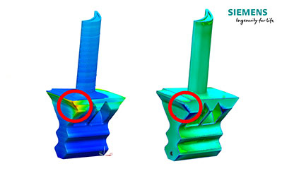
Consider launch of a new “Digital Twin” Process Simulation solution for predicting distortion during 3D printing. When metal parts are 3D printed and the layers build up, residual heat from fusing the layers can cause parts to warp inside the printer, causing various problems, from structural issues within the part itself to print stoppage. Simulation of the printing process can solve many of these problems.
The Process Simulation solution uses a Digital Twin to simulate the build process prior to printing, anticipating distortion within the printing process and automatically generating the corrected geometry to compensate for these distortions.
We tried many tools to get to the final iteration. You can see in the picture we show two design iterations—the middle one that is still quite similar visually to the original node was our first iteration. And you can see version 2.0, the second iteration is where we really made the big step with the freedom of form.
Using generative design, engineers specify parameters, such as weight-to-strength ratios, efficient material use, and temperature, pressure and force ranges. The generative design engine creates several design options through an iterative approach. Engineers then evaluate and select from among the generatively designed options—more options than would be possible with traditional design tools, and likely many options that the engineers would never have considered.
No one group has complete control over the final results, so it is a lot of different engineers have to move at the same time or at least following in a series, and what you see in these processes is that they all start with great concepts but throughout the phases they become victim to planning pressure and costs so a lot of new ideas and challenges are just designed out.
Now we have a digital representation of what the designer/customer wants, we have the actual part that we can touch and feel and also a Digital Twin of that actual part. In 3D printing we can only work in the digital world with a 3D digital model of the desired component. Now we can build the part, according to the 3D model, take that physical component and carry out our own 3D scan, creating yet another 3D model.
Digital Twin of the actual part can then be sent back to the designers and he can compare what we have manufactured to what his model wants, and even use the actual part model to simulate its impact, digitally, in the final design.
In the case of a 3D printer, we’re building a Digital Twin of a build process and recording the slightest defects, deviations and other build characteristics. With Digital Twins, models will continually be updated with each new build and become ever smarter in recognising and troubleshooting any potential issues that might arise.
Not only will there be a Digital Twin of the component, showing the internal and external requirements, but also a Digital Twin of the process that made that part; the process parameters, how long did the build take, how many layers were built, were there any issues.. all of these aspects building a digital picture of the part enabling further analysis and confidence in final applications of components.
Next generation of Digital Twins incorporate information from other sensors monitoring the 3D printing process, such as the shape of the pool of metal rendered molten by the laser. In addition, this smart, real-time quality control will not function in isolation.
The power of Digital Twins is their ability to share insights with each other. So you can imagine many 3D print machines sharing unique build insights with each other that makes them each more informed about what to watch for during a build process.
Through the Digital Twin process, you can accelerate the production of mission-critical equipment. Using Digital Twin technology, we’re aiming to rapidly speed up the time that parts could be re-engineered or newly created using 3D printing processes.
The key challenge with 3D printing is being able to additively build a part that mirrors the exact material composition and properties of the original part that was formed through subtractive measures. With operation of mission-critical parts there is no room for deviations in material performance or manufacturing error.
Properties and serviceability of 3D printed components are affected by their geometry, microstructure and defects. These important attributes are currently optimised by trial and error because the essential process variables can’t currently be selected from scientific principles.
A solution is to build and validate a Digital Twin of the 3D printing process capable of predicting of the spatial and temporal variations of metallurgical parameters affecting the structure and properties of components.
In principal, the Digital Twin of 3D printing process , when validated with accurate with experimental data would replace or reduce expensive, time consuming physical experiments with rapid inexpensive numerical experiments. In the initial phase, the Digital Twin would consider all the important 3D print process variables as input and provide a transient 3D model.
What Process Was Used To Make the Prototype?
Metal 3D printing and vacuum casting are great for making prototypes. Each process can be a little slow per part, but that’s not really an issue if you just want one or a few. But when scaling up to low-volume production for a new product launch, different manufacturing solutions should be considered. In the case of a vacuum cast prototype, for example, it makes sense to choose plastic injection molding for larger quantities.
Injection molding differs from vacuum casting in many important ways, both in how the process is done as well as the results obtained. First, it requires that a hard tool be made from aluminum or steel. And injection molding rewards close adherence to design rules that don’t come into play in vacuum casting. These can include the dimensions of ribs and bosses, the use of gussets, minimal wall thicknesses, draft angles, the positions of gates, runners, ejector pins and many other considerations.
So product developers must ensure that their plans account for the additional cost and time-to-market that a transition from one process to another will involve.
Will The Results Be The Same?
A single part made by CNC machining will not be identical to a counterpart made via pressure die casting, and the differences can be both cosmetic as well as mechanical.
Each process introduces its own set of variables that can affect quality. For instance, die cast parts must contend with porosity, and porosity might limit the part’s strength or affect the surface finish – which is not true with a CNC machined part made out of the same raw material.
Understanding this in advance will help a product developer to calculate costs, development lead times and engineering and testing protocols for the finished part.
What Material Was Used?
Another consideration is the choice of material. A prototype, by its nature, can be made of most anything. When ramping up from prototype to new product introduction, it’s best to avoid hard-to-find, expensive or hard-to-work-with materials. The cost and time constraints of production favor the use of materials that can be purchased readily in the commercial market in sufficient quantities without supply interruption and which can be processed efficiently.
This could compromise the look and feel of the final part compared to the prototype, but this can perhaps be compensated for by using alternate finishing techniques.
What Was The Finishing Process?
A prototype that was carefully sanded, polished and hand painted with a custom color no doubt looks great. But is that practical on a large scale? Elaborate finishes tend to require a lot of attention to detail and careful hand work. This is simply not practical for volume production unless the intention is to deliberately target high-end clients. For most products on the shelf, it’s necessary to find solutions that reduce hand work to a minimum.
Processes that can be automated are one way. Another possible solution is to stick to one kind of finish rather than multiple finishes, each of which would need to be handled separately and which would represent a much larger investment in time and money.
How Many Components in the Build?
As with complex hand work, it’s also best to limit the number of individual components to a minimum for volume production. Fewer parts require less assembly, for one thing, but also represent less of a risk for breakage, loss, out-of-tolerance specifications and potential variation from one production batch to another. For volume production, minimising every variable is the best way to both save money and maintain consistent quality.
Keep it Simple
Production places a premium on repeatability and consistency, minimising costs, automating processes, and using simplified materials that are easily available. The engineering and design skills needed to fulfill these criteria may be different than those used to come up with the initial great idea. You can contract out to offer advice and alternative solutions when you upload your CAD drawings for a free quotation.
Rapid prototyping helps companies turn ideas into realistic proofs of concept, advances these concepts to high-fidelity prototypes that look and work like final products, and guides products through a series of validation stages toward mass production.
Engineers and designers have been creating hardware prototypes for decades, but the tools, materials, and methods used to create those prototypes have made tremendous progress. With rapid prototyping tools like 3D printers, product development teams can create prototypes directly from CAD data, and quickly execute rounds of design revisions based on real-world testing and feedback at a substantially lower cost than ever before.
Prototyping with 3D printers, however, can be quite different than with working with other traditional tools or outsourcing to machine shops and service providers. Cost factors, efficiencies, and design rules often don’t directly translate.
In this guide, we collected ten insights to help you optimise your 3D printing rapid prototyping workflow to be as cost and time efficient as possible, from choosing a technology to practical design tips.
1. Prototype In-House
For any business involved in prototyping, one of the first questions that comes up is whether to order prototypes from service contractors and machines shops or to purchase equipment to prototype in-house.
Rapid prototyping stops being rapid when an outsourced part takes multiple days or even weeks to arrive. Outsourcing can quickly become expensive when a project requires dozens or more iterations. On the other hand, purchasing a variety of machinery to produce all the different parts in a single product often requires substantial investment, a dedicated location, and expertise to operate.
The answer is not always clear-cut, but the best practice for most companies is to bring the most frequently used prototyping tools in-house and outsource larger parts, and parts that require non-standard materials or complex machinery.
Smaller desktop or benchtop 3D printers can cover many of the prototyping needs for most companies. They’re fast, easy to use, can operate in small shops and require minimal training. Depending on the number of parts and printing volume, investment in a desktop 3D printer can break even within months and save weeks or months of lead time over the course of development.
2. Choose the Right Technology and Machinery
To find the right prototyping materials and equipment, first, consider what you need from your prototypes. Do you need prototypes for visual demonstration only or for testing the mechanical attributes of your product?
Understanding these needs will help you choose the right technology. For example, for basic concept models the only requirement could simply be speed—finish and details may not matter. Looks-like prototypes, however, may require technologies and materials designed for fine details and high-quality surface finishes, while functional prototypes might need to withstand mechanical stress or have specific properties, such as optical transparency.
3. Automate Post-Processing
Post-processing is an often overlooked, but potentially time-consuming aspect of prototyping with 3D printing. Some technologies require less post-processing than others, but all 3D printed parts require a certain degree of post-processing. Some aspects of post-processing can be automated to reduce labor time and costs.
.
4. Assemble Large Parts From Multiple Prints
3D printing large parts can be a costly and lengthy process, often requiring outsourcing parts to service providers with large industrial printers. But, just as assemblies consist of many individual building blocks, splitting a model into smaller parts is a great solution to creating objects larger than what fits into the build volume of a 3D printer.
You can add features to your design that will allow the prints to align themselves, or simply split the parts with straight cuts, requiring you to align them during the fastening process.
When selecting a bonding method, your primary consideration should be the strength of the bonded joints, which is dependent on the ultimate use case of the parts such ask a bonding agent for art, scale models, and complex shapes that are not meant for functional use and to sustain impact.
5. Make Parts Hollow
By default, most 3D printers create fully dense parts. When you’re not printing functional parts that require a certain strength, hollowing out large and bulky designs can be a great way to save a considerable amount of material and printing time.
6. Adjust Layer Height
Adjusting the layer height is a great way to reduce printing time. On some systems the difference between parts printed with 50 and 100 micron layers is often barely noticeable, but reduces printing time by 50%.
7. Optimise Schedule
There are a few methods for optimising your printing schedule to get the highest throughput possible, printing close to 24 hours a day. Best practices for optimising schedule include Batch multiple parts into one build, printing small, shorter runs during the day and large builds overnight, using multiple printers to distribute the workload and increase same-day throughput and using Dashboard to receive alerts when a print finishes and to manage and watch multiple printers remotely.
8. Reduce or Eliminate Support Structures
A poorly oriented part can result in excessive support structures. Excessive supports use more material, increase printing time, and require more post-processing time. Depending on your design, a part can often be printed with limited or without any support structures. Most print preparation tools allow you to experiment with different part orientations and check how different setups affect overall print time and material usage before printing.
A manifold prototype printed directly on the build platform with limited support structures for overhanging features. Some technologies might also be better suited to your designs than others. Some printers often require excessive support structures for designs with complex shapes, angles, and overhangs. Support structures on printers are easy to break away and support requirements can be reduced with smart tools. Some machines do not need support structures at all, as the powder acts as a support for the parts while printing.
9. Optimise the Design
While 3D printers offer a high degree of design freedom, a bit of time spent on optimising part geometries goes a long way to ensure efficient printing of high-quality parts. When designing a part for 3D printing, make sure to follow design guidelines for the specific technology or printer.
Common optimisations include: Maintaining wall thicknesses at or above minimum specifications, Eliminating or supporting angled walls and steep overhangs, Adding drain holes for hollow designs, and using lattice structures to achieve an ideal balance between part strength, material usage, and print speed.
10. Prevent Failures
Failed parts and broken machinery wastes expensive engineering time and can set development cycles back by days or even weeks. Fortunately, 3D printers have developed tremendously since the first desktop printers entered the market a decade ago and professional 3D printers today are tools that companies can rely on.
As a rule of thumb, you can reduce failures to statistical insignificance by following some simple rules: Work with reliable machines and companies that provide training and technical support, Keep your machine and workspace clean, Take the time to set up your prints properly, Print only with reliable, tested materials, Check the expiration date of materials before printing and Carry out regular service and maintenance as specified by the manufacturer.
 RSS Feed